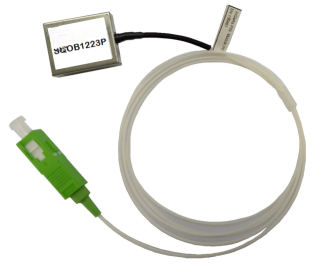
The SQOB1223 Optical Receiver Block is a single-mode fiber pigtailed module featuring a low-noise, impedance-matched broadband photodiode and RF amplification.
The device receives optical analog and/or digital signals for a range of video broadcast options, and delivers the corresponding RF electrical output. The wide bandwidth supports the delivery of up to 110 CATV analog channels or a combination of analog and digital channels (80/30 for example), including HDTV broadcast.
The device exhibits excellent distortion performance with values well above standards over the entire bandwidth and case temperature specifications (47 to 1218 MHz, - 30 to +85 °C).
Moreover, the proprietary impedance-match circuitry between the photodetector and RF amplification stages provides a very low noise performance value, typically less than 4.5 pA/√Hz.
The device can be used in both 1310 nm and 1550 nm applications being useful at different points of a given network.
Features
l 47 to 1218 MHz Bandwidth Supports as Many as 110 CATV Analog Channels or a Combination of Analog and Digital Channels Including HDTV Broadcast.
l Excellent RF Frequency and Distortion Characteristics for High Linearity.
l Low Noise (4.5 pA/√Hz typ.) and Low Power Dissipation (0.75 W max.) as well as High RF Output.
l Internal Proprietary Impedance Match Circuitry (75Ω)
l Robust Small Package with Single-Mode Fiber Pigtail and Connector Options
l Wide Operating Case Temp Range, - 30 to + 85°C
Applications
l Video Signal Distribution in HFC and FTTx nodes
Specifications:
Table 1. Performance Highlights
Parameter | Limits |
Frequency Range | 47 - 1218 MHz |
CTB (79ch NTSC) | -80 dBc (typ) |
CSO (79ch NTSC) | -68 dBc (typ) |
Optical Input Power | Up to +3 dBm |
Wavelength | 1260 - 1620 nm |
Power Consumption | 0.85 W |
Table 2. Electrical/Optical Characteristics
Parameter | Unit | Min | Typ | Max | Symbol |
Optical Power | dBm | -- | -- | +3 | PIN |
Optical Return Loss | dB | 40 | -- | -- | RLOPT |
DC Power +5V Amp Bias, (Pin 2) +12V PD Bias, (Pin 6) |
mA mA |
-- -- |
-- -- |
160 3 |
ICCA ICCP |
Wavelength | nm | 1260 | 1310/1550 | 1620 | λ |
Responsivity | mA/mW mA/mW | -- -- | >0.85 at 1310 nm >0.95 at 1550 nm | -- -- |
-- |
PDI Monitor Voltage | V/mA | -- | 0.5 | -- | VMON |
Dissipation | W | -- | -- | 0.85 | PDISS |
Table 3. RF Characteristic
Parameter | Unit | Min | Typ | Max | Symbol |
Frequency Range | MHz | 47 | - | 1218 | BW |
Ripple (47MHz - 1218 MHz) | dBpk - pk | - | 1 | 1.2 | - |
Tilt | dB | - | 1 | 2 | - |
RF Output Level 2 | dBmV / ch | 22 | - | 24 | RFOUT |
Output Return Loss (47 - 1218 MHz) | dB | - | - | -14 | RL |
Equivalent Input Noise | pA/√Hz | - | - | 4.5 | EIN |
Discrete Second-Order 1 | dBc | - | -70 | -67 | DSO |
Discrete Third Order 1,3 | dBc | - | -85 | -80 | DTO |
Note: 1. Two laser test at 1310 nm/1550 nm. 40% OMI/tone. Total received optical power = 0 dBm. Distortion products measured at 40 and 200 MHz.
2. Optical Input = 0 dBm, OMI = 20%
3. DTO may degrade to -77 dBc above 800 MHz
Handling Procedures
Please observe the following precautions to avoid damage:
Fiberglass optical coupling
Maximum tensile strength = 5 N. Minimum bending radius = 35 mm.
Static Sensitivity
Gallium Arsenide Integrated Circuits are sensitive to electrostatic discharge (ESD) and can be damaged by static electricity. Proper ESD control techniques should be used when handling these devices.
Absolute Maximum Ratings
Parameter | Unit | Rating |
Optical Input Power | mV | 5 mW |
DC Supply Over-Voltage (5 minutes) | V | 30 |
Storage Temperature | °C | - 40 to +100 |
Operating Mounting Base Temperature | °C | - 30 to +100 |
 Caution! ESD sensitive device.
  RoHS
RoHS
Alarm: Exceeding any one or a combination of the Absolute Maximum Rating conditions may cause permanent damage to the device. Extended application of Absolute Maximum Rating conditions to the device may reduce device reliability. Specified typical performance or functional operation of the device under Absolute Maximum Rating conditions is not implied.
Package Drawing (Dimensions in millimeters)


Pinning:
PIN | Description |
1 | GND |
2 | + 5 |
3 | GND |
4 | RF OUT |
5 | GND |
6 | + 12 V |
7 | PD MONITOR |
8 | GND |
Description | Part Number |
SQOB1223 Optical Receiver Block, with SC/APC Connector | 9945000007 |
SQOB1223 Optical Receiver Block, with FC/APC Connector | 9945000008 |


 苏公网安备32050902102581号