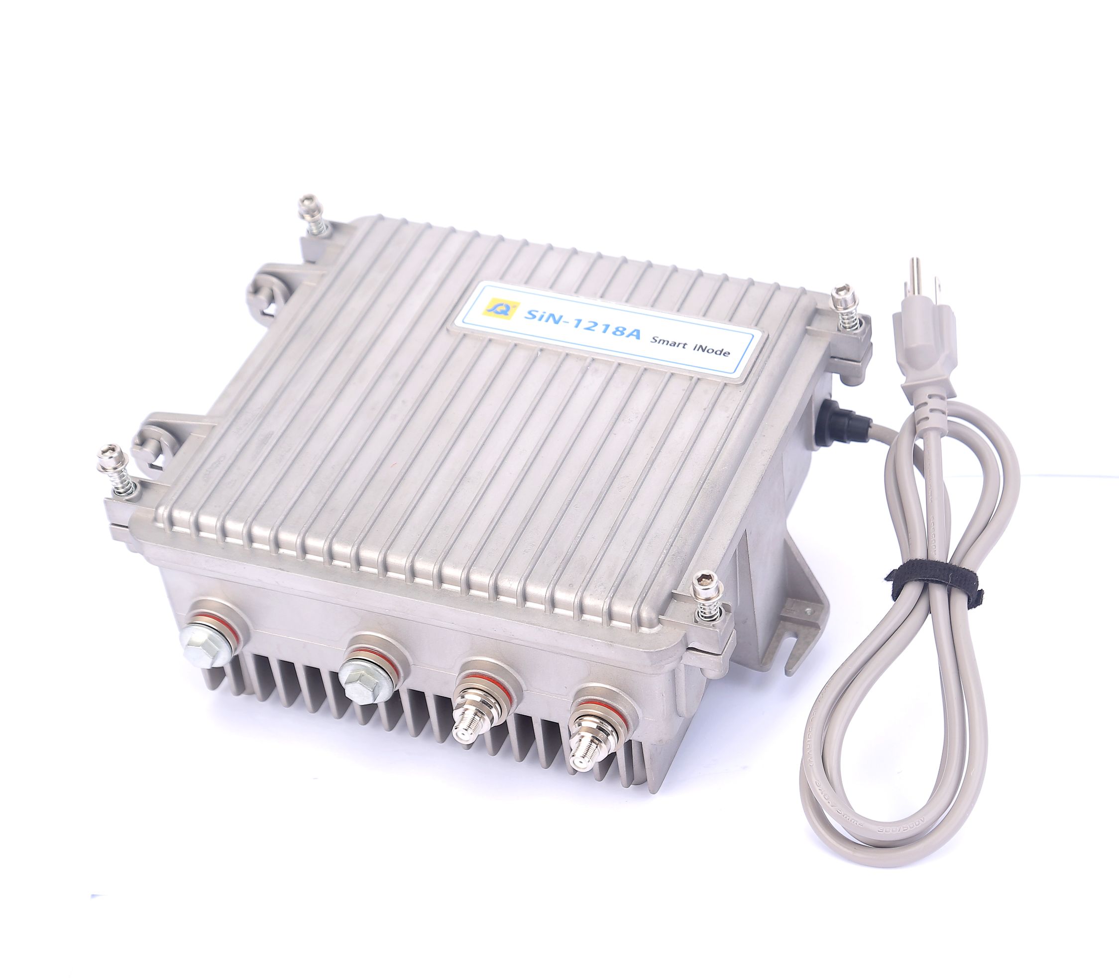
The SiN-1218A Smart iNode is designed to serve as an intelligent node within today’s HFC networks. It can be adjusted via Local Control Software (LCS) a computer or tablet. The device's USB port communicates directly to the Smart iNode controller. The no-touch Smart iNode delivers an innovative approach that enables significant operational savings for operators through automation. No manual configuration is necessary.
Features
l Supports 1.2 GHz
downstream
l 58 dBmV high RF output
level @ 1.2 GHz
l AGC optical input range of
- 8 to + 2 dBm
l No needed of installing
and maintaining any external accessories such as pads and EQs
l Local monitoring, control
and set up via Local Control Software(LCS) or mobile APP
l Current adjustment for the forward output gain block
for power saving according to composite power loading
l Shut down gain-block independently
on interstage amplifier to save power
l Switch & attenuator
for reverse path gain adjust and turn-off for diagnose and control
l DC voltage monitor capable
l Second output can be
selected via splitter
Specifications
Table 1. Forward Section Specifications
|
Item |
Units |
Value |
|
Optical Section |
||
|
Wavelength |
nm |
1310 and 1550 |
|
Optical Input Power Range |
dBm |
- 8 - + 2 |
|
Optical AGC Range |
dBm |
- 8 - + 2 |
|
RF
output level at 0 dBm optical input @ 3.25 % OMI |
dBmV |
281 |
|
Optical Return Loss |
dB |
45 |
|
Optical Connector |
- |
SC / APC |
|
RF Section |
|
|
|
Frequency Range |
MHz |
105 - 1218 |
|
Frequency Response |
dB |
± 0.75 |
|
Internal Tilt (linear) |
dB |
16 - 22 |
|
RF Output Level |
dBmV |
58 @ 1218 MHz, 1 output |
|
Return Loss |
dB |
16 |
|
Launch Amplifier Section |
|
|
|
Frequency Range |
MHz |
54 - 1218 |
|
Operational Gain |
dB |
26 - 46 (@ 1218MHz) |
|
Frequency Response |
dB |
± 0.75 |
|
Internal Tilt (linear) |
dB |
222,3 |
|
Return Loss |
dB |
16 |
|
Noise Figure |
dB |
3 |
|
Reference Output Tilt |
dB |
222,4 |
|
RF Test Point |
dB |
20 ± 0.5 |
|
Distortion Section5,6,7,8 |
|
|
|
C/N |
dB |
53 |
|
Distortion CTB CSO XMOD |
dBc |
63 62 59 |
Note:
1.
Minimum receiver RF output
level for the stated transmitter percent OMI per channel, with receiver optical
input power of 0 dBm. To determine RF output levels at other optical input
power levels, add (or subtract) 2 dB in RF level for each 1 dB increase (or
decrease) in receiver optical input power.
2.
Reference output tilt and
internal tilt are both “Linear” tilt.
3.
Forward internal tilt
specified is primarily due to interstage equalizer and output equalizer on
board.
4.
The forward reference
output tilt specified is the internal tilt of the launch amplifier and the tilt
associated with the optical link.
5.
The tilt is defined as the
difference between the gain at the start frequency and the gain at the stop
frequency 22dB tilt.
6. VO=58dBmV
at 1218MHz, 22dB tilt, 79 analog channels plus 111 digital channels.
7.
79 analog channels, NTSC
frequency raster: 55.25MHz to 547.25MHZ, +36dBmV to 45.4dBmV tilted output
level, plus 111digital channels, -6dB offset relative to the equivalent analog
carrier.
8.
Composite Second Order
(CSO) – the CSO parameter (both sum and difference products) is defined by
ANSI/SCTE6. Composite Triple Beat (selective voltmeter method), referenced to
100% modulation of the carrier being tested. Carrier to intermodulation Noise
(CIN) – The CIN parameter is defined by ANSI/SCTE17.
|
Item |
Units |
Value |
|
|
Optical Section |
|||
|
Laser Type |
- |
DFB |
|
|
Wavelength |
nm |
1310,
1550, CWDM, DWDM |
|
|
Output Power |
dBm |
3 |
|
|
Optical Return Loss |
dB |
45 |
|
|
Optical Connector |
- |
SC / APC |
|
|
RF Section |
|||
|
RF Input Level |
dBmV |
0 - 10 |
|
|
Frequency Range |
MHz |
5 - 85 |
|
|
Frequency Response |
dB |
± 0.50 |
|
|
Internal Tilt (linear) |
dB |
± 0.50 |
|
|
Return Loss |
dB |
16 |
|
|
NPR Dynamic Range |
dB |
20 @ 30 dB NPR |
|
|
Launch Amplifier Section |
|
|
|
|
Frequency Range |
MHz |
5 - 85 |
|
|
Operational Gain |
dB |
161 |
|
|
Frequency Response |
dB |
± 0.50 |
|
|
Internal Tilt (linear) |
dB |
± 0.50 |
|
|
Return Loss |
dB |
16 |
|
|
Noise Figure |
dB |
6.5 |
|
|
RF Switch Loss |
dB |
60 |
|
|
RF Test point |
dB |
20
± 0.5 |
|
Notes: 1. Reverse operational gain is measured from the reverse RF input port to the reverse transmitter and includes optical interface board gain.
Table 3. General Specifications
|
Item |
Units |
Value |
|
Supply
Voltage |
VAC |
110 - 250 |
|
Power Consumption |
W |
32 |
|
RF
Connectors |
- |
F - female, Imperial |
|
RF
Impedance |
Ω |
75 |
|
Operating
Temperature |
˚C |
-
40 - + 60 |
|
Humidity |
% |
5 - 95 %,non-condensing |
|
- |
IP 65 |
|
|
Dimensions
(W x H x D) |
mm |
240 x 205
x 120 |
|
Weight |
kg |
2.5 |
Note: Unless otherwise noted, all specifications reflect typical performance and are referenced to 68°F (20°C). Specifications are based upon measurements made in accordance with SCTE/ANSI standards (where applicable), using standard frequency assignments.
|
Description |
Part
Number |
|
SiN-1218A Smart iNode, 1.2GHz, 85/105, SC/APC, 1310nm Reverse Transmitter, 230V, European Plug |
9930000450 |


 苏公网安备32050902102581号